Version: w26.1.1
Latest updates made on 3/20/2026
AER Embedded Systems Documentation
Welcome to the software and systems doc page for Anteater Electric Racing. This site is the shared starting point for onboarding, architecture, and implementation details across the team.
Start Here:
- New to the project? Begin with onboarding:
- Looking for system-level context?
Subteam Split
Data Acquisition (DAC)
The DAC side focuses on telemetry transport, storage, visualization, and simulation tooling.
- CAN ISO-TP telemetry ingestion and decoding (CAN docs)
- MQTT broker startup and configuration (MQTT docs)
- Telemetry fan-out to MQTT and TDengine (Send docs)
- Dashboard + Raspberry Pi telemetry services
- Simulator efforts (Godot, inverter simulation, RL) (Simulator docs)
Firmware
Firmware owns embedded control and safety-critical behavior on vehicle modules.
- CCM control firmware (sensor I/O, control logic, telemetry) (CCM Overview)
- PCC firmware for precharge sequencing and HV/LV safety interactions (PCC Overview)
- FreeRTOS task scheduling and CAN message flow (Tasks & Scheduling)
- Vehicle state machine, fault handling, power limiting, and wheel-speed sensing
Current Focus Areas
- Transitioning codebase to comp car with new Motor + Inverter
- CAN interrupt robustness and queue overflow validation
- Shock sensor integration and calibration for suspension telemetry
- Launch control tuning and slip-ratio based torque shaping
- Power limit behavior around rule thresholds and low-SOC derating
- Continued simulator expansion and PCC subsystem documentation
Contributing to Docs
This site is built with mdBook and Mermaid support.
- Add or update markdown pages under
src/ - Keep navigation in sync through
src/SUMMARY.md - Run locally with
mdbook serve
If you are unsure where new content belongs, start in the relevant onboarding page and link deeper implementation details from there.
Author: Alistair Keiller
Onboarding
Relevant coding background to understand DAC
Git: Video || Article Rust: Book && Rustlings Cargo: Guide (sections 1-2, optionally 3) Iced.rs: Short Guide Tokio.rs: Tutorial
Relevant hardware background to understand DAC
Raspberry Pi 5: Fun Video Teensy 4.1: Fun Video CAN protocol: Video
Codebase overview
Here is our codebase: https://github.com/Anteater-Electric-Racing/embedded
fsae-dashboard
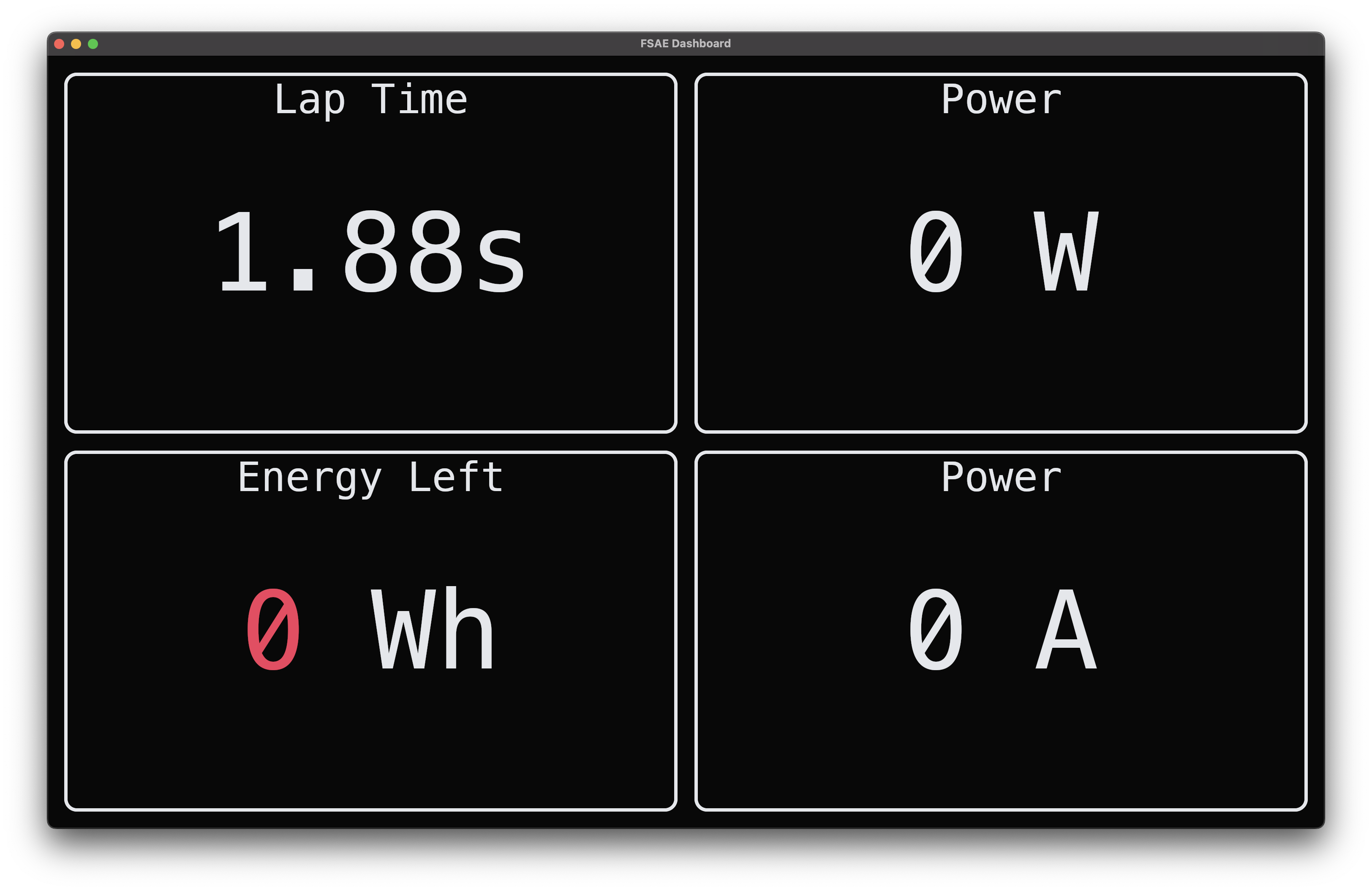
This dashboard displays current critical information to the driver.
fsae-raspi
Runs on the Raspberry Pi and handles all telemetry ingestion and storage. It polls ISO-TP CAN data from can0, decodes it into typed telemetry, and fans it out to an embedded rumqttd MQTT broker and a TDengine time-series database.
See the CAN docs, MQTT docs, and Send docs for details.
Author: Mikayla Lee
AER Telemetry over CAN ISO-TP
Overview
This system receives motor-controller telemetry over CAN ISO-TP, decodes it into strongly typed data, and forwards it for downstream processing. It also includes vCAN-based test utilities for CI.
Function: read_can_hardware
Purpose: Continuously reads and decodes telemetry packets from can0
Workflow:
- Opens an ISO-TP socket on
can0(source ID0x666, destination ID0x777) - Retries socket creation on failure with a 1-second backoff
- Reads incoming packets asynchronously, validates packet length, and parses raw bytes into
TelemetryDatausing Deku - Captures a timestamp with
now_ms()and forwards viasend_message(data, ts)
Error Handling:
- Logs socket creation failures and malformed packets
- Logs packets with trailing bytes after decode
- Re-enters socket setup if packet reads stop or fail
Function: read_can
Dispatches to hardware ISO-TP reception (can0) or synthetic mode when the synthetic feature flag is enabled.
Function: read_can_synthetic
Publishes default TelemetryData at a ~1 ms interval for testing and CI. Logs throughput approximately once per second.
Struct: TelemetryData
Represents a fully decoded MCU telemetry packet received over CAN ISO-TP. Fields are decoded little-endian from a fixed-layout binary frame.
| Field | Type | Notes |
|---|---|---|
apps_travel | f32 | Normalized accelerator pedal travel |
bse_front | f32 | Front brake sensor |
bse_rear | f32 | Rear brake sensor |
imd_resistance | f32 | Isolation monitoring measured resistance |
imd_status | u32 | Raw IMD status bits — interpret against MCU spec |
pack_voltage | f32 | HV pack voltage |
pack_current | f32 | HV pack current |
soc | f32 | Battery state of charge |
discharge_limit | f32 | Current discharge limit |
charge_limit | f32 | Current charge limit |
low_cell_volt | f32 | Minimum cell voltage |
high_cell_volt | f32 | Maximum cell voltage |
avg_cell_volt | f32 | Average cell voltage |
motor_speed | f32 | Motor rotational speed |
motor_torque | f32 | Instantaneous output torque |
max_motor_torque | f32 | Configured torque limit |
motor_direction | MotorRotateDirection | |
motor_state | MotorState | |
mcu_main_state | MCUMainState | |
mcu_work_mode | MCUWorkMode | |
mcu_voltage | f32 | MCU DC bus voltage |
mcu_phase_current | f32 | MCU phase current |
mcu_current | f32 | MCU current draw |
motor_temp | i32 | Motor temperature |
mcu_temp | i32 | MCU temperature |
mcu_warning_level | MCUWarningLevel | Aggregated MCU warning severity |
shocktravel1–4 | f32 | Shock travel channels 1–4 |
dc_main_wire_over_volt_fault | bool | |
motor_phase_curr_fault | bool | |
mcu_over_hot_fault | bool | |
resolver_fault | bool | |
phase_curr_sensor_fault | bool | |
motor_over_spd_fault | bool | |
drv_motor_over_hot_fault | bool | |
dc_main_wire_over_curr_fault | bool | |
drv_motor_over_cool_fault | bool | |
dc_low_volt_warning | bool | |
mcu_12v_low_volt_warning | bool | |
motor_stall_fault | bool | |
motor_open_phase_fault | bool | |
over_current | bool (1 bit) | System-level protection flag |
under_voltage | bool (1 bit) | Supply below valid range |
over_temperature | bool (1 bit) | Temperature exceeded safe limit |
apps | bool (1 bit) | APPS fault flag |
bse | bool (1 bit) | BSE fault flag |
bpps | bool (1 bit) | BPPS fault flag |
apps_brake_plaus | bool (1 bit) | Accelerator/brake plausibility violation |
low_battery_voltage | bool (1 bit) | Battery low warning; followed by 24-bit pad |
Author: Lawrence Chan
MQTT Broker
Overview
mqttd() loads the embedded rumqttd.toml config, builds a rumqttd::Broker, and starts it.
Function: mqttd
Workflow:
- Reads
../rumqttd.tomlviainclude_str!. - Builds
config::Configfrom TOML. - Deserializes into broker config.
- Creates
Broker::new(config)and callsbroker.start().
Error Handling:
- Logs and returns if config load fails.
- Logs and returns if config deserialization fails.
- Logs if broker startup fails.
Author: Alistair Keiller
Telemetry Fan-Out (MQTT + TDengine)
Overview
send_message() serializes a telemetry reading once, attaches a ts field, then fans out to both MQTT and TDengine.
Function: send_message
Workflow:
- Serialize message to JSON; insert
tswith the provided timestamp. - Publish JSON to MQTT topic
T::topic()at QoSAtMostOnce. - Convert to TDengine schemaless line protocol and enqueue for write.
Backpressure / error behavior:
- Serialization failure → log, drop
- MQTT queue full → warn, drop; publish error → log
- Line protocol conversion failure → log, drop
- TDengine queue full → warn, drop; channel error → log
Runtime Singletons
get_mqtt_client — lazily creates an AsyncClient (OnceCell), spawns the MQTT event loop. On poll error: logs and retries after 1 second.
get_tdengine_sender — lazily creates a channel sender (OnceCell), ensures the fsae database exists, and spawns 4 worker tasks sharing one receiver. Workers batch up to 5,000 records per write. After 10 consecutive write failures, drops and recreates the database.
Trait: Reading
Requires Serialize. Implementors define topic() -> &'static str to specify the MQTT/TDengine measurement name.
Function: now_ms
Returns current UNIX time as milliseconds (u64).
Virtual Simulator for Vehicle Testing
Author: -
Godot Game Engine Simulation
Author: Lawrence Chan
Overview
Virtual simulation utilizing Godot Game Engine for testing vehicle characteristics / autonomous driving.
Vehicle Controller Script (Godot – VehicleBody3D)
Overview
This script implements a basic vehicle controller for a Godot VehicleBody3D node.
It handles:
- Acceleration and engine force
- Braking
- Steering control
- Natural deceleration
- Speed limiting
- Debug speed output
The script reads player inputs and updates the physics behavior of the vehicle’s VehicleWheel3D nodes accordingly.
Node Requirements
The script must be attached to a VehicleBody3D node.
The vehicle should contain child nodes of type:
VehicleWheel3Dwithuse_as_traction = true(drive wheels)VehicleWheel3Dwithuse_as_steering = true(steering wheels)
Input Controls
| Key | Action |
|---|---|
| W | Accelerate |
| A | Turn left |
| S | Brake |
| D | Turn right |
| C | Reset steering to center |
These must be mapped in Project Settings → Input Map:
acceleratedeceleratesteer_leftsteer_rightsteer_center
Configuration Constants
Debug
const DISPLAY_DEBUG_SPEED = true
Prints vehicle speed and steering data to the console.
Engine / Acceleration
| Constant | Description |
|---|---|
| MAX_POWER | Maximum engine force |
| ACCELERATION_STEP | Increment applied to engine force when accelerating |
| USE_DYNAMIC_THROTTLE | Enables dynamic throttle based on speed |
| MOTOR_RAMP_DOWN_STEP | Rate engine force decreases when not accelerating |
Braking
| Constant | Description |
|---|---|
| BRAKING_STEP | Brake force increment |
| BASE_DECEL | Passive braking when no throttle is applied |
| MAX_BRAKING | Maximum brake force |
Steering
| Constant | Description |
|---|---|
| STEER_STEP | Steering change per frame |
| MAX_STEERING_ANGLE | Maximum wheel steering angle in degrees |
Speed Limit
const MAX_VEHICLE_SPEED_MPH = 90.0
Maximum allowed vehicle speed.
Internally the script uses m/s and km/h, converting to mph only for debug display.
Core Variables
| Variable | Purpose |
|---|---|
| previous_displayed_speed | Prevents duplicate debug prints |
| steer_normalized | Normalized steering value for debugging |
Utility Functions
Degree / Radian Conversion
func deg_to_rad(deg):
    return deg * PI / 180

func rad_to_deg(rad):
    return rad * 180 / PI
Used for steering calculations.
Speed Conversion
func kph_to_mph(kph) -> float:
    return kph / 1.609
Converts kilometers per hour to miles per hour.
Throttle Function
func throttle_function(current_speed) -> float:
    # Connect engine power data here
    return 1000.0
Returns engine force when dynamic throttle is enabled.
This is currently a placeholder and can be replaced with a realistic engine torque curve.
Normalized Steering Angle
func norm_steering_angle(steer: float) -> float:
    return steer * (90/PI)
Converts steering radians into a normalized value for debugging.
Physics Update Loop
Main vehicle logic runs inside:
func _physics_process(delta: float) -> void:
This function performs:
- Input processing
- Debug speed calculation
- Wheel physics updates
Speed Calculation
Vehicle speed is calculated from the body’s velocity:
var velocity_mps = linear_velocity.length()
Conversions:
- m/s → km/h:
mps * 3.6 - km/h → mph:
kph / 1.609
Example debug output:
VEHICLE SPEED | 72 km/h [20 m/s] (45 mph) | STEER: 0.4
Wheel Processing
The script loops through all child nodes:
for object in get_children():
If the node is a VehicleWheel3D, it is processed depending on its role.
Traction Wheels
If:
wheel.use_as_traction
The script applies engine and braking forces.
Acceleration
Engine force increases while:
- Below
MAX_POWER - Below
MAX_VEHICLE_SPEED
Braking
Brake force increases up to:
MAX_BRAKING
Engine force is set to zero when braking.
Natural Deceleration
When neither accelerating nor braking:
- Engine force gradually decreases
- Base braking (
BASE_DECEL) is applied
Steering Wheels
If:
wheel.use_as_steering
The script adjusts the wheel steering angle.
Steering changes are converted from degrees to radians because Godot steering uses radians.
Steering Limits
Maximum steering range:
± MAX_STEERING_ANGLE
If exceeded, the value is clamped.
Steering Reset
Pressing C resets steering:
wheel.steering = 0.0
Vehicle Behavior Summary
| Behavior | Description |
|---|---|
| Acceleration | Applies engine force to traction wheels |
| Braking | Applies brake force and disables engine force |
| Steering | Rotates steering wheels within limits |
| Natural slowdown | Engine force gradually decreases |
| Speed limiting | Prevents vehicle exceeding maximum speed |
| Debug output | Displays speed and steering data |
Possible Improvements
- Implement a realistic engine torque curve
- Add gear ratios and transmission
- Implement traction control
- Add drift or slip simulation
- Display speed using a UI element instead of console output
Example Node Structure
VehicleBody3D
│
├── VehicleWheel3D (FrontLeft)
├── VehicleWheel3D (FrontRight)
├── VehicleWheel3D (RearLeft)
└── VehicleWheel3D (RearRight)
Typical configuration:
| Wheel | Traction | Steering |
|---|---|---|
| Front Left | No | Yes |
| Front Right | No | Yes |
| Rear Left | Yes | No |
| Rear Right | Yes | No |
Summary
This script provides a basic but functional vehicle physics controller using Godot’s built-in vehicle system.
It demonstrates:
- Player input handling
- Vehicle physics updates
- Wheel-based acceleration and steering
- Debug speed monitoring
The system is designed to be simple, modular, and easily extendable for more advanced driving simulations.
Inverter Simulation
Author: -
Reinforcement Learning
Godot RL Agents Integration for Autonomous Driving
Author: Mikayla Lee
Overview
The Godot RL Agents integration enables reinforcement learning agents to train autonomous driving policies on the AER simulator. This system bridges the Godot physics simulator with RL training libraries, allowing any standard AI RL agents to learn driving behaviors in a virtual environment.
The integration serves as the interface layer between:
- Godot car physics simulator
- Stable-Baselines3 PPO training algorithms
- Future autonomous driving control systems
System Architecture
The RL training pipeline consists of:
- GodotEnv Wrapper - Connects RL agents to the Godot simulator
- Action Space - Defines steering and throttle controls (2D continuous space)
- Observation Space - Captures car telemetry (position, velocity, speed)
- PPO Training Model - Implements Proximal Policy Optimization for policy learning
- Reset/Step Functions - Handles episode management and action execution
The system uses the Godot RL Agents library to establish direct communication between the Python training environment and the Godot game engine, eliminating the need for manual WebSocket implementation.
Implementation Details
Environment Configuration
class GodotCarEnv(GodotEnv):
    def __init__(self, env_path=None, port=11008, show_window=True, seed=0):
        super().__init__(
            env_path=env_path,
            port=port,
            show_window=show_window,
            seed=seed
        )
The environment wrapper inherits from GodotEnv and manages:
- Connection to Godot executable on port 11008
- Visual rendering control for training monitoring
Action Space
Actions are represented as a 2D continuous vector [steering, throttle]:
| Control | Range | Mapping |
|---|---|---|
| Steering | -1.0 to 1.0 | -20° to +20° |
| Throttle | -1.0 to 1.0 | Full brake to full gas |
Observation Space
The agent receives 7D telemetry data per timestep:
- Position (x, y, z) - 3D coordinates in world space
- Velocity (vx, vy, vz) - 3D velocity vector
- Speed - Scalar magnitude of velocity
Training Pipeline
The system uses Proximal Policy Optimization (PPO) with the following arameters:
| Parameter | Value | Purpose |
|---|---|---|
| Learning Rate | 3e-4 | Gradient descent step size |
| Steps per Update | 2048 | Experience collection before update |
| Batch Size | 64 | Mini-batch size for optimization |
| Epochs | 10 | Training iterations per update |
| Gamma | 0.99 | Discount factor for future rewards |
Integration Workflow
The RL training loop operates as follows:
-
Start:
reset()resets car to starting position → returns initial observation -
Action Execution:
Agent predicts action based on current observation →step(action)sends controls to Godot -
Simulation Update:
Godot applies physics, updates car state → returns new observation and reward -
Learning:
PPO updates policy based on collected experience → repeat until convergence
This cycle runs for 100,000 timesteps during initial training, with the trained model saved for deployment.
Current Status & Next Steps
Completed:
- Researched and integrated Godot RL Agents library
- Implemented GodotEnv wrapper with action/observation spaces
- Configured PPO training pipeline with Stable-Baselines3
- Established reset/step function architecture
In Progress:
- Creating basic test simulator in Godot to validate integration
- Working with other daq members to fully integrate RL wrapper with car physics simulation
Future Work:
- Implement reward shaping for racing-specific behaviors (staying on track, lap time optimization)
- Add termination conditions (crash detection, lap completion)
Dependencies
pip install godot-rl stable-baselines3
References
Onboarding
Author: Karan Thakkar
Relevant coding background to understand firmware
C++ reference and language: cppreference.com PlatformIO: platformio.org — helpful for faster prototyping and device management.
FreeRTOS official site and API reference: freertos.org
Debugging & diagnostics
- TBD (openCD?)
Relevant hardware background to understand firmware
Teensy 4.1: PJRC Teensy 4.1 - MCU board used in our stack
CAN protocol: Video
Custom PCBs
CCM
Controls all the sensor inputs + outputs and perform motor control calculations.
PCC
Automates the battery precharge sequence to mimize instaneous capacitor charging.
Codebase overview
Here is our codebase: https://github.com/Anteater-Electric-Racing/embedded
fsae-vehicle-fw
Contains all vehicle firmware for CCM (sensor interfacing + motor controls)
fsae-pcc
Contains all firmware for PCC sequence.
Author: Karan Thakkar
System Architecture
---
config:
  theme: 'base'
  themeVariables:
    primaryColor: '#ffffffff'
    primaryTextColor: '#000000ff'
    primaryBorderColor: '#17007cff'
    lineColor: '#000000ff'
    secondaryColor: '#f3f3f3ff'
    tertiaryColor: '#f3f3f3ff'
---
flowchart BT
    %% This is a comment for the entire diagram

     subgraph CAN[" "]

            BMS(Orion BMS 2)
            BC(Battery Charger)
            PCC(PCC - Teensy 4.0)
            INV(OMNI Intervter)
            RPI(Raspberry Pi)
            MOTOR(Motor) === INV
        end

        CCM(CCM - Teensy 4.1)


        %%CAN LOOP1
        BMS <--> |CAN1| BC <--> |CAN1| PCC <---> |CAN1| CCM

        %%CANLOOP2
        INV<-----> |CAN2|CCM<---> |CAN1 + CAN2|RPI


        subgraph Analog[Analog]
            direction LR
                B(Brake Sensors)
                A(Pedal Position Sensors)
                LPOT(Suspension Travel Sensors)
                TR(Thermistors)
        end

        subgraph PWM[PWM]
            direction LR
                W(WheelSpeed Sensors)
                FP(Fans & Pumps)
                SP(Speaker & Amp)
        end
        subgraph MISC[Digital]
            direction LR
                RTM(Ready To Move Button)
                BL(Brake Light)
        end

        Analog --> CCM
        PWM --> CCM
        MISC -->CCM
---
config:
  theme: 'base'
  themeVariables:
    primaryColor: '#ffffffff'
    primaryTextColor: '#000000ff'
    primaryBorderColor: '#17007cff'
    lineColor: '#000000ff'
    secondaryColor: '#f3f3f3ff'
    tertiaryColor: '#f3f3f3ff'
---
flowchart LR
PCC(Precharge Status) --> CCM
A(Analog Inputs) --> CCM
D(Digital Inputs) --> CCM
CCM(Teensy MCU) --> IC(Inverter Commands) --> Motor(Motor Control)
CCM --> Raspi(Raspi) --> Dashboard(Dashboard: Driver + Pit)
CCM --> PWM(PWM Output) --> CC(Cooling Control)

style CCM fill:#00FF00,stroke:#333,stroke-width:2px
Tasks and Threads
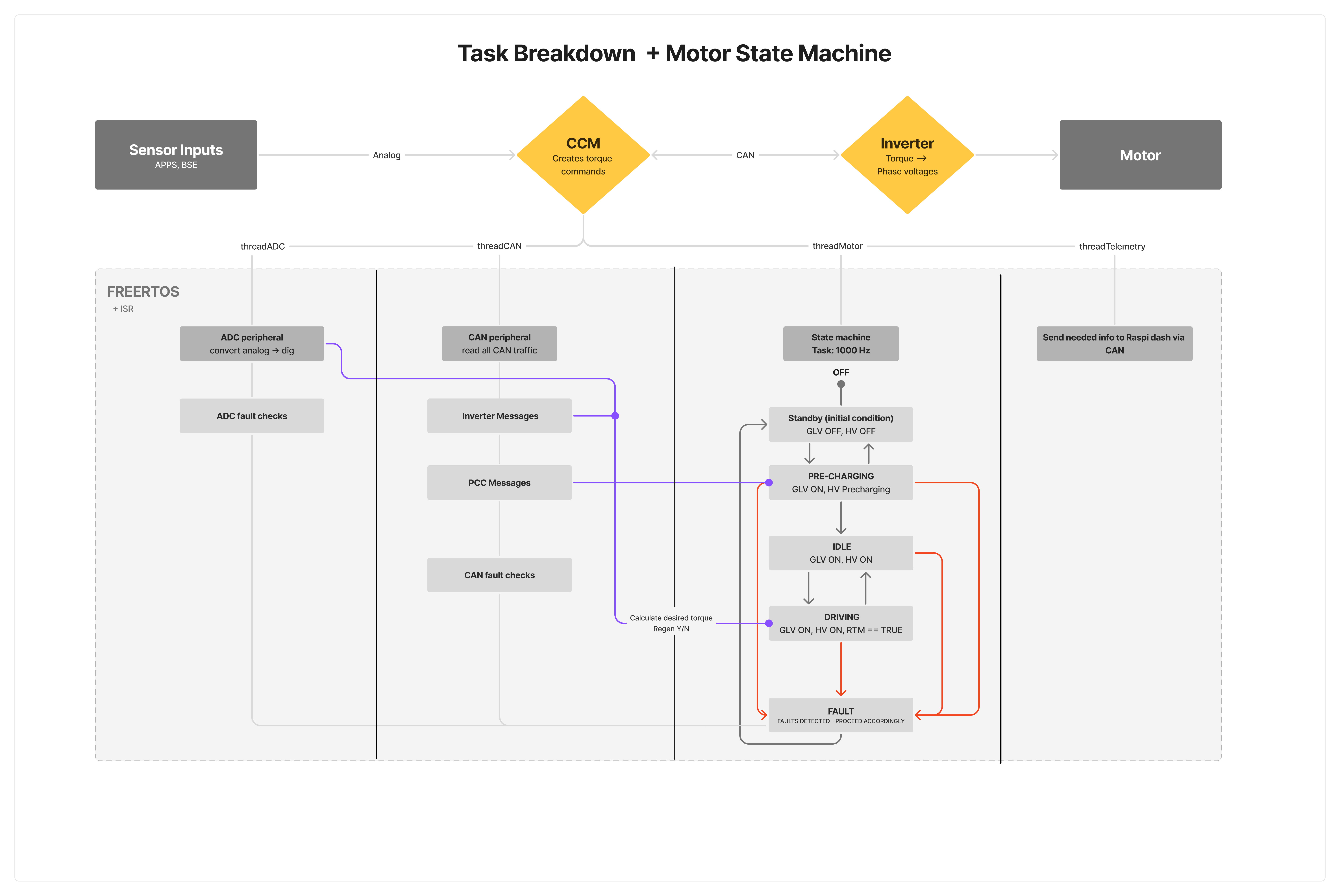
Author: Karan Thakkar
CCM: Central Computer Module
CCM is the main central vehicle board. Its main purpose is to acquire data from sensors across the car, use it in vehicle control commands and send over CAN to our Raspberry Pi.
CCM is powered by (1) Teensy 4.1 MCU which runs an ARM-Cortex-M7. We write our firmware in C++ and flash it to our board. The board communicates with various devices over analog, digital, CAN and i2C.
The full kicad files can be found here.
Current Version: 2.0
Schematic
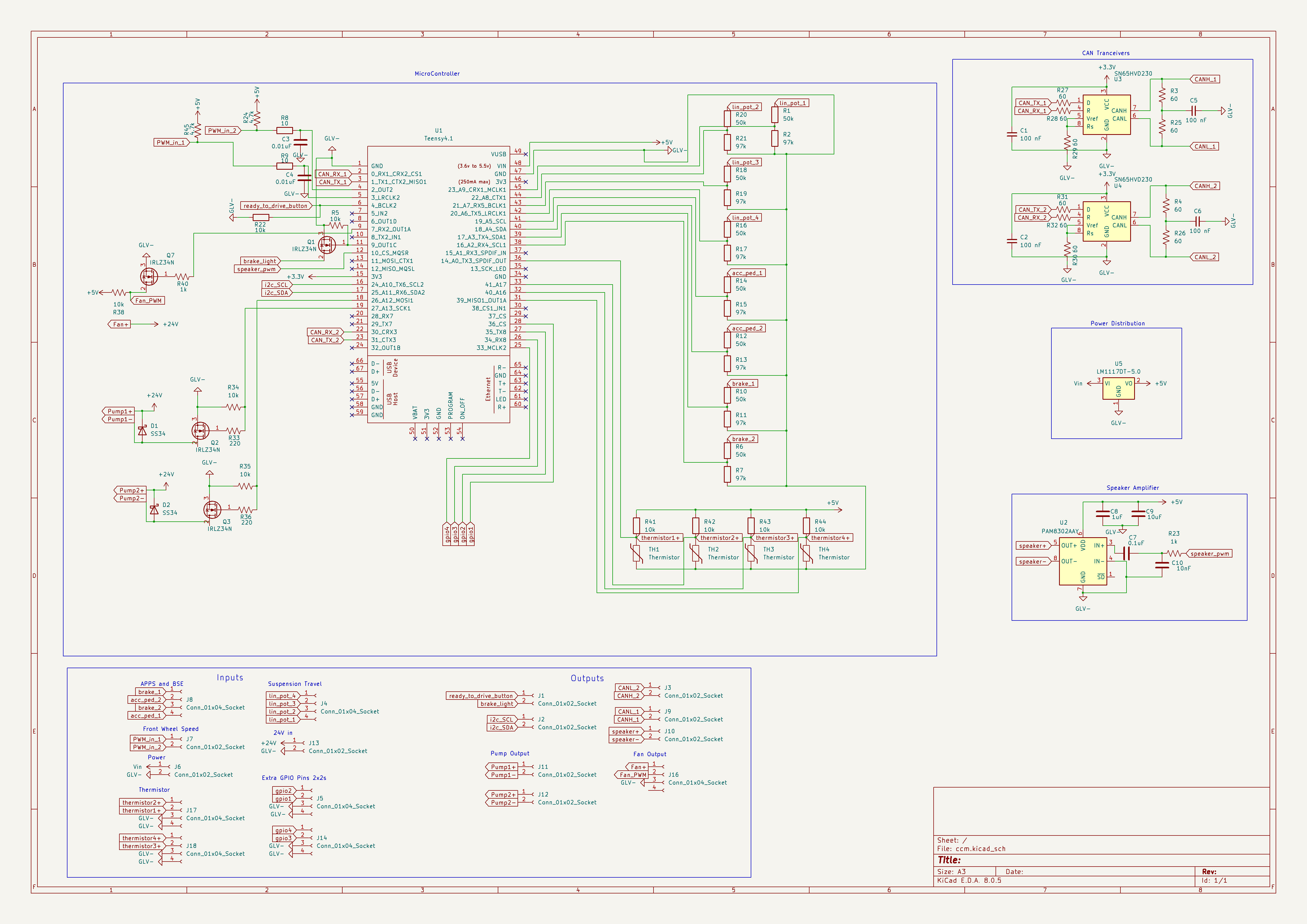
- The top left shows the MCU pinout
- The top right shows the CAN Tranceiver setup
- The bottom shows the I/O
PCB Layout
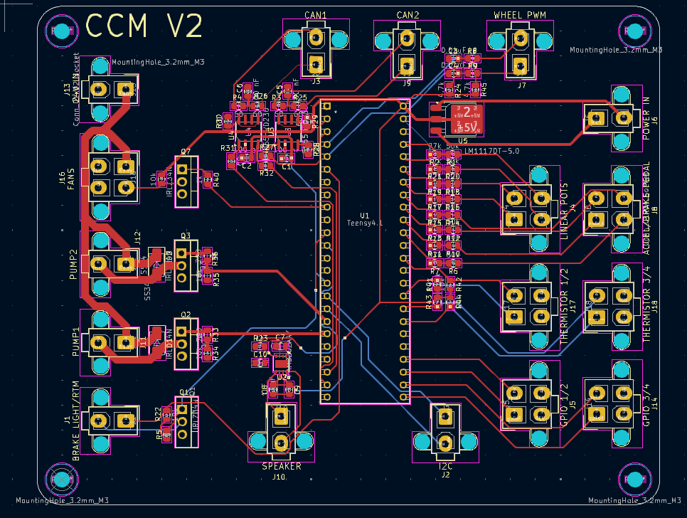
- The Right side holds all the analog inputs + 12v Power in
- The left side holds CAN1/CAN2 + PWM outputs from CCM as well as misc inputs.
Improvements
This board has planned improvments for a version (3.0) Some new features include
- More sensors inputs (Tire Temp, Brake Temp, Steering Wheel Angle)
- Input for Inverter Keyswitch (KL15)
Author: Karan Thakkar
Peripherals
Digital I/O
RTM (Ready To Move) Button Input
The RTM input is handled as a standard digital GPIO read. It functions as a momentary push-button with software debouncing to avoid false triggering from mechanical bounce. Each press toggles the latched internal state between 0 and 1, allowing the system to reliably detect transitions. This signal is used in the vehicle state machine to move the car from the IDLE state into the RUNNING or DRIVE state once all safety conditions are met.
Brake Light Output
The brake light is driven as a digital output that activates based on braking conditions. Depending on system rules and logic, this signal can be turned on when:
- Brake pressure exceeds a threshold
- Regenerative braking torque is applied above a defined amount
- Other system-defined braking conditions are met The output is typically a high-side digital drive that activates the physical brake lamp in accordance with FSAE regulations.
Wheel Speed Sensors (WSS) Input
Author: Dylan Tran
Wheel speed sensors on all four wheels are hall-effect pickups producing a square-wave digital signal proportional to wheel rotation. Hardware interrupts trigger on the falling edge of these pulses to increment dedicated counters for each wheel.
This system ensures the vehicle can accurately monitor individual wheel speeds, allowing for traction control, odometry, telemetry, and dynamic vehicle control.
The firmware computes wheel rotational dynamics over a fixed 100ms interval utilizing the accumulated pulse count, the number of sensor teeth, and the wheel circumference.
Fans & Pumps Output
Two MOSFET-controlled outputs are available for driving the cooling fan and coolant pump. These are controlled through software feedback loops that monitor thermistor temperature readings. When temperature increases beyond a target setpoint, fan or pump duty cycle increases proportionally. When temperatures fall below defined limits, duty cycle is reduced. This provides automatic thermal regulation for the accumulator or power electronics cooling loop.
Ready to Drive Sound
Authors: Dylan Tran, Anushree Godbole
Audio signaling is performed using a PWM output connected to a low-pass filter and amplifier, which drives the tactile transducer. This is used to produce a tone for the Ready to Drive Sound (RTDS). A tactile transducer was selected in place of the conventional speaker to save space on the car. The tactile transducer is mounted on the car’s aerobody, which acts as a sound-radiating element.
The RTDS system ensures the car meets FSAE safety requirements for audible signaling before the drivetrain engages.
The Ready to Drive Sound is a continuous tone lasting 1–3 seconds (EV.9.7.2), triggered during the vehicle startup sequence.
Testing Results: Testing was performed by gradually increasing the supply voltage to 24 V and setting the amplifier potentiometer to its maximum position to verify compliance with the 80dB @ 2m requirement (EV.9.7 and IN.10.3).
Testing was performed in two rounds. In the first round, a standalone Teensy 4.1, low-pass filter, amplifier, and the tactile transducer was mounted directly on KiloZott’s aerobody (in ELF). The sound level was measured using a smartphone sound meter application, which recorded a peak sound level of 95 dB at a distance of 2 meters and an average sound level of approximately 90 dB over a 30-second period. During this test, tones ranging from 1 Hz to 1500 Hz were played in a continuous loop.
In the second round of testing, the components (Teensy 4.1, low-pass filter, and amplifier) were already integrated on Safety Board and CCM, which were harnessed together for testing. Since MegaZott’s aerobody was not yet available, a metal sheet was used as the mounting surface during this test in ECT. An exact sound pressure level was not recorded during the second test. Subjectively, the output volume was comparable to that measured during the first test, which exceeded the 80 dB requirement at 2 meters.
Based on testing results, the final RTDS implementation uses a 1300 Hz tone played for 3 seconds.
| Measurement Distance | Sound Level | Voltage | Status |
|---|---|---|---|
| 2 meters | 95 dB | ~24V | PASS |
Analog I/O
Brake System Encoder
A linear analog pressure transducer is used to measure hydraulic brake line pressure. The voltage is read via an ADC and mapped into engineering units using a calibration curve. Brake pressure is used to:
- Smoothly blend mechanical and regenerative braking
- Block acceleration torque while braking
- Activate brake lights
- Support telemetry and control algorithms
This sensor is part of multiple safety-critical paths and must be sampled and checked reliably.
Acceleration Pedal Position
The accelerator pedal position sensor outputs a variable voltage proportional to throttle demand. The reading is converted into a normalized torque request and fed into the torque controller. For safety, dual redundant channels are commonly monitored, and mismatches are checked to detect faults such as wiring damage or sensor failure. If readings disagree beyond limits, torque is disabled and a fault is raised.
Suspension Travel
Suspension position is measured by analog linear potentiometers These readings allow:
- Logging for vehicle dynamics analysis
- Dynamic control adjustments such as damping or traction control
Thermistors
Thermistors measure temperature in critical subsystems such as:
- Motor controllers
- Batteries and accumulator modules
- Cooling loops
- Power electronics
These readings are used in closed-loop thermal regulation. Raw voltage readings are converted using standard thermistor curve equations or lookup tables. If temperatures exceed defined safety thresholds, torque may be reduced, cooling activated, or the vehicle shut down depending on severity.
CAN
BMS
The Battery Management System communicates via CAN, sending essential data such as:
- Cell voltages
- Module temperatures
- Current consumption
- State-of-Charge and State-of-Health
- Fault flags and system warnings
The control system must consume these messages to maintain safe vehicle operation. If BMS signals a critical fault, the drivetrain must disable torque output immediately.
Battery Charger
During charging mode, the onboard charger exchanges CAN messages with the BMS and vehicle controller. Messages include:
- Charging current and voltage targets
- Charge state progress
- Fault and error reporting
The charger generally follows BMS instructions to ensure safe constant-current and constant-voltage charging curves.
PCC
The PCC (Pre Charge Circuit) communicates over CAN to exchange infor with the CCM. Data typically includes:
- Precharge state
- Precharge Progress
- TS/Accum Voltage read over frequency to voltage circuits
- Precharge time
The PCC and CCM coordinate to ensure safe charing of the inverter and HV side. Read more about this in the PCC section.
CCM
The CCM (Central Computer Module) acts as the main MCU for car.
- Broadcast system heartbeat messages
- Reads all sensor readings
- Receive driver input and button states
- Relay fault conditions
- Coordinate operation between subsystems
- Sends torque commands to the Inverter based on all readings
- Relays info to telemetry side.
Purpose
Process two pedal sensors and output a safe, normalized throttle value.
- Converts raw ADC → pedal % (0–1)
- Ensures both sensors agree
- Detects faults (electrical + plausibility)
- Prevents brake + throttle simultaneously
High Level Flow
Raw ADC → Filter → % Mapping → Voltage Check → Faults → Output
Update Function
APPS_UpdateData(raw1, raw2)
- Filter Inputs
- Apply low-pass filter (100 Hz)
- Smooths noise and spikes
- This helps keep the pedal signal stable instead of jumping around from tiny electrical fluctuations
- Convert to Pedal %
- Uses calibrated raw values:
rest → 0%
full → 100%
apps1 = LINEAR_MAP(raw1, REST1, FULL1, 0 → 1)
apps2 = LINEAR_MAP(raw2, REST2, FULL2, 0 → 1)
- This means the code is mainly built around real measured ADC values from the pedal, not just ideal voltages
- That makes calibration easier because the mapping matches the actual installed hardware
- Clamp Values
- Ensure:
0 ≤ APPS ≤ 1
- If the sensor goes slightly below rest or above full travel, the final output is still kept in a safe range
- Convert to Voltage Used for fault detection only:
voltage = ADC_VALUE_TO_VOLTAGE(raw)
- The code still converts raw readings into voltage so it can check for open-circuit or short-circuit behavior
- So percentage is based mainly on raw ADC calibration, while voltage is used mainly for electrical safety checks
- Voltage Safety Check
APPS1 (3.3V):
0.33V → 2.97V (fault range)
APPS2 (5V):
0.5V → 4.5V (fault range)
- If a sensor voltage goes outside these ranges for too long, the system raises an APPS fault
- This helps catch wiring issues, sensor faults, or readings that are no longer physically believable
- Sensor Agreement Check
difference = |APPS1 - APPS2|
If:
difference > 0.1 (10%)
→ FAULT
- Since the pedal uses two sensors, they should track each other closely
- If they disagree too much, the system treats that as unsafe
- Brake Plausibility Check
If:
Throttle > 25%
AND
Brake > threshold
→ FAULT
Reset when:
Throttle < 5%
- This prevents the car from accepting heavy throttle while strong braking is also being detected
Output
APPS = (APPS1 + APPS2) / 2
- The final pedal command is the average of both sensors
- This gives one clean throttle value to pass into the rest of the vehicle logic
ADS1115 Integration
The APPS code is fed by the ADS1115 external ADC.
In adc.cpp, the ADS reads the two pedal channels and passes them into:
APPS_UpdateData(raw1, raw2);
So the flow is:
Pedal sensor → ADS1115 → raw ADC counts → APPS_UpdateData()
Why use the ADS1115?
The ADS1115 gives 16-bit readings, which means it can measure the sensor signal with much finer resolution than a typical 12-bit onboard ADC.
That helps because:
- higher resolution gives smaller voltage steps between readings
- better precision makes pedal calibration cleaner
- less quantization error means smoother percentage mapping
- less noise sensitivity makes the signal easier to filter and trust
In simple terms, the ADS gives the APPS module a more detailed picture of what the pedal is doing.
Why that matters for APPS
Since APPS is safety-critical, better signal quality is valuable:
- small pedal changes are easier to detect
- the filtered signal is smoother
- the two sensors can be compared more accurately
- fault checks become more reliable
So while the APPS logic itself is mainly based on filtered raw counts and calibration, the ADS1115 improves the quality of those raw counts before APPS ever sees them.
Summary
APPS:
- Converts pedal → throttle
- Verifies sensor agreement
- Blocks unsafe conditions
The ADS1115 helps by giving high-resolution 16-bit sensor readings with better accuracy and lower effective noise, making the APPS signal cleaner and more trustworthy before torque is commanded.
Author: Pranav Kocharlakota and Wilson Nguyen
ADC Interrupt Handler
Functional Architecture
The sensor acquisition subsystem replaces a classic manual analog reading strategy—where the processor would explicitly halt execution to read pins one by one—with a hardware-driven, zero-overhead pipeline. When triggered by hardware timers, the system automates sensor sampling, sequences the channel configuration, and transfers the data directly to memory using Direct Memory Access (DMA).
This approach eliminates CPU polling overhead entirely. The processor remains completely unaware of analog conversions until an entire frame of critical vehicle data (comprising suspension linpots, throttle, and brake sensors) is cleanly packaged in RAM.
Integrated Hardware Sequencing
The subsystem links several internal microcontroller blocks into an automated pipeline that operates independently of the core processor:
- PIT (Periodic Interrupt Timer): Fires hardware trigger signals at a fixed rate of 1kHz. PIT0 and PIT1 are intentionally phase-offset by 50 microseconds to stagger conversion waves and prevent electrical noise or power dips from corrupting consecutive samples.
- XBAR (Cross-bar Switch): Routes the hardware pulses directly from the PIT timers to the ADC_ETC hardware trigger slots without utilizing interrupt service routines.
- ADC_ETC (ADC External Trigger Control): Configured to manage two distinct conversion chains containing 4 sensor channels each. Upon receiving an XBAR pulse, it automates channel rotation, commands the hardware ADC to convert the pins, and sequences results into a dense register window.
- DMA & Ping-Pong Buffers: As soon as the second chain finishes converting, the DMAMUX signals the DMA controller. The DMA engine executes a minor-loop copy, moving the entire 12-word data frame out of the ADC_ETC registers and dropping it into one half of a dual ping-pong buffer in RAM.
Memory Management & Data Processing
To ensure the decoder task never reads half-written or corrupted data, the subsystem implements a 32-byte aligned ping-pong buffer strategy (adc_dma_buffer[2][8]).
While the DMA engine is actively populating active_buffer, the processing thread is safely decoding the static data stored in ready_buffer. Because the processor utilizes a data cache that could cause it to read stale memory state, the DMA_ISR explicitly clears the CPU cache line using arm_dcache_delete immediately after a transfer finishes.
Once the cache is cleared and the buffer indexes flip, the handler issues a fast FreeRTOS task notification to wake the threadADC decoder task. The decoder reads the raw values out of the completed buffer and immediately forwards them to their respective device processing modules:
- Chain 0 (Linear Pots 1–4): Dispatched via
ShockTravelUpdateData()to track suspension dynamics. - Chain 1 (APPS 1–2 & BSE 1–2): Dispatched via
APPS_UpdateData()andBSE_UpdateData()to feed torque commands and brake plausibility checks into the VCU core.
Execution Constraints
The DMA_ISR runs at maximum hardware priority, blocking all normal vehicle thread execution until it exits. Doing any actual sensor processing, calibration, or mathematical scaling inside this handler would stall the VCU and risk missing timing deadlines for high-priority tasks like the CAN transmit loops.
The handler is strictly confined to clearing flags, swapping the active buffer pointer, invalidating the CPU cache, and unblocking the decoder thread. The actual parsing and downstream distribution of the sensor data happens safely at normal priority inside the decoupled threadADC loop.
Author: Karan Thakkar
Vehicle Control
Motor/Inverter
The motor inverter in this system is responsible for controlling how power flows from the high-voltage battery to the traction motor, and its behavior is managed through a well-defined state machine aligned with Formula SAE Electric vehicle requirements.
The inverter is commanded through CAN messages that include torque requests, motor mode, relay control, and system readiness.
Depending on the operating state—such as OFF, STANDBY, PRECHARGING, IDLE, DRIVING, or FAULT—the inverter receives different command values that ensure the vehicle only delivers torque when it is electrically safe to do so. During driving, the requested torque is converted into a percentage value that the inverter understands, while additional parameters like regen mode, gear mode, and allowable currents from the BMS are also communicated. This helps maintain smooth torque delivery and ensures that high-voltage operation meets safety rules set by FSAE.
The transitions between inverter states are based on system conditions such as the Ready-To-Move button, precharge status, BMS confirmations, and overall system health.
For example, the inverter does not enter the DRIVING state until the precharge process has completed, battery relays are confirmed closed, and the driver actively requests propulsion. If communication issues or electrical faults occur, the inverter is immediately commanded into a FAULT state to disable torque and open relays where needed.
By structuring inverter behavior around explicit state transitions and safety checks, the system guarantees predictable and rules-compliant operation while providing clear separation between low-voltage logic and high-voltage power control, which is a core requirement for competition-legal and reliable Formula SAE EV design.
State Machine
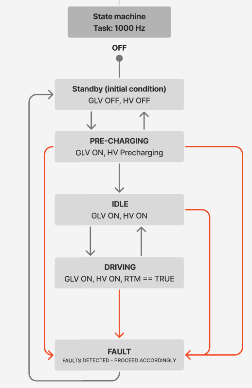
Fault Handling
This fault map system uses a single 32-bit variable to keep track of all vehicle faults. Each fault type has its own bit in the bitmap, and when a fault is detected, its bit is turned on. When the fault clears, the bit is turned off. This makes fault storage very compact and fast to check, which is helpful on embedded systems where memory and CPU time matter. The system can quickly tell if any fault is active or look at specific bits to see which ones are triggered.
The handler function then looks at the bitmap and sets the motor into a fault state if any fault is active. Right now, every fault is treated the same, but the structure is flexible enough to customize actions later, such as limiting torque for minor issues or shutting down the drivetrain for serious ones. This design keeps the code organized, easy to maintain, and simple to expand as the system grows.
Traction Control Module
Author: Atharva Rao
Purpose
The traction control module prevents rear-wheel spin during acceleration by reducing the torque request sent to the inverter. It compares front (undriven) wheel speeds to the motor-derived rear wheel speed to detect slip, then applies a PID correction when slip exceeds a defined ratio.
Control Method
Slip Calculation
Slip is computed in VCU_GetSlip() using motor eRPM as the driven wheel speed reference, which is calculated through pole pairs and gear ratio:
motor_speed = (eRPM / POLE_PAIRS) / GEAR_RATIO
slip = (motor_speed − front_wheel_avg) / front_wheel_avg
The calculation also consists of an additional step: if the two front wheel speeds differ by more than MAX_SPEED_DIFF (35 RPM), the lower reading is used instead of the average to guard against a faulty sensor pulling the wheel speed reference high.
If the front wheel average falls below MIN_SPEED (5 RPM) — i.e., the car is nearly stationary, the function returns the target slip ratio directly, avoiding a division-by-near-zero.
PID Torque Reduction
The PID controller targets SLIP_RATIO (0.10) as its setpoint. Its output is a multiplicative reduction applied to the driver’s requested torque:
target = requested_torque − (requested_torque × PID_output)
This means that the correction scales with the driver’s pedal demand. For example, a large torque request gets a larger absolute cut when the calculated slip is high.
Note: The PID output is constrained so the torque cannot be increased beyond what the driver requested (This is implemented to abide by the rules).
Test Cases
Constants assumed: POLE_PAIRS = 10, GEAR_RATIO = 3, MIN_SPEED = 5 RPM, MAX_SPEED_DIFF = 35 RPM, SLIP_RATIO = 0.10, TC_KP = 0.5, TC_KI = 0.01, TC_KD = 0.0
Test Case 1 — No Slip
WSS1 = 100 RPM, WSS2 = 100 RPM, eRPM = 300000
requested_torque = 200 Nm
slip = (100 − 100) / 100 = 0.00
PID output = 0.5 × (0.00 − 0.10) = −0.05 → clamped to 0
torqueDemand = 200 Nm (unchanged)
Test Case 2 — Slip At Threshold
WSS1 = 100 RPM, WSS2 = 100 RPM, eRPM = 330000
requested_torque = 200 Nm
motor_speed = (330000 / 10) / 3 = 110 RPM
slip = (110 − 100) / 100 = 0.10
PID output = 0.5 × (0.10 − 0.10) = 0.00
torqueDemand = 200 Nm (unchanged)
Test Case 3 — Moderate Slip
WSS1 = 100 RPM, WSS2 = 100 RPM, eRPM = 360000
requested_torque = 200 Nm
motor_speed = (360000 / 10) / 3 = 120 RPM
slip = (120 − 100) / 100 = 0.20
PID output = 0.5 × (0.20 − 0.10) = 0.05
torqueDemand = 200 − (200 × 0.05) = 190 Nm
Test Case 4 — Heavy Slip
WSS1 = 40 RPM, WSS2 = 42 RPM, eRPM = 300000
requested_torque = 200 Nm
motor_speed = (300000 / 10) / 3 = 100 RPM, front_avg = 41 RPM
slip = (100 − 41) / 41 = 1.44
PID output = 0.5 × (1.44 − 0.10) = 0.67
torqueDemand = 200 − (200 × 0.67) = 66 Nm
Current Limitations
- PID gains (
TC_KP,TC_KI,TC_KD) are placeholder values and require tuning. - The target slip ratio (0.10) might require tweaking for effective traction control.
- Testing is yet to be done to ensure everything works well.
Purpose
Design a function that optimizes 0–60 mph acceleration by adjusting torque output based on slip ratio.
- Optimal slip ratio ≈ 7% (commonly 5–10% depending on car).
- If slip ratio exceeds optimal → decrease torque
- If slip ratio falls below optimal → increase torque
Algorithm Overview
Initial Function
- Validate and reset PID gains and internal PID state.
- Obtain constants (max torque, optimal slip target).
- Initialize launch control button to false (inactive until pressed).
Update Function
-
Check button state
- If not pressed → output driver torque normally.
-
Wheel speeds
- Controlled speed: rear wheel with higher speed.
- Free rolling speed: front wheel with lower speed.
-
Slip Ratio
- slip = (controlledSpeed - freeRollingSpeed) / freeRollingSpeed
-
Torque Logic
- If slip < 0.05 → increase torque.
- If slip > 0.10 → decrease torque.
- PID Correction
- Run at 100 Hz (
dt = 0.01). - Use
PID::PID_Calculate()for correction. - Add correction to driver torque.
- Clamp Torque
- If corrected torque > max → clamp to maxTorque.
- If < 0 → clamp to 0 Nm.
Implementation Details
void launchControl_Init()
Initializes PID controller values for slip ratio correction.
void threadLaunchControl(void *pvParameters)
LAUNCH_STATE_ON
- Obtain slower front wheel speed.
- Convert rad/s → m/s using wheel radius.
- Motor/rear speed used as controlled speed.
- Compute slip.
- PID applies torque correction.
- Clamp torque within bounds.
- If brakes are pressed → exit to LAUNCH_STATE_OFF.
LAUNCH_STATE_OFF
- Wait for:
- Front brake fully pressed
- Motor speed = 0
- Then activate launch control (FSAE requires button activation — must update logic).
FAULT State
- Triggered by irregular wheel speeds or invalid conditions.
TESTING PLAN
Method Signature:
threadLaunchControl(void *pvParameters)
Constants:
slipTarget = 0.7f

minTorque = 0.0f

maxTorque = 260.0f

wheelRadius = 0.35f
TestCase 1 (base case)
Brake = 60 psi
Motor speed = 0 rad/s
Motor state = MOTOR_STATE_DRIVING
threadLaunchControl()
launchControlState -> LAUNCH_STATE_ON
TestCase 2
wheelSpeedFL = 80 rad/s, wheelSPEEDFR = 82 rad/s, motorSpeed = 80 rad/s
realTorque = 150 Nm
LaunchState = on
Slip ratio = 0.0–0.02 -> small PID correction
torqueDemand = 150 Nm (unchanged to barely changed)
LaunchState = ON
TestCase 3
wheelSpeedFL = 40 rad/s, wheelSpeedFR = 42 rad/s, motorSpeed = 100 rad/s
realTorque = 200 Nm
Slip ratio = (100–41)/41 = 1.43 -> very high slip
PID correction negative -> torque reduced near 0 Nm
torqueDemand = near minTorque = around 0 Nm
TestCase 4
wheelSpeedFL = 100, wheelSpeedFR = 99, motorSpeed = 100
realTorque = 250 Nm, slip slightly below 0.07
PID positive correction increases torque above 260 -> clamped at 260 Nm
torqueDemand = 260 Nm
TestCase 5
LaunchState = ON, BSE_GetBSEReading() -> 80 PSI
APPS_GetAPPSReading() < 1.0
Expected behavior:
PID reset
torqueDemand = rawTorqueInput
launchControlState = LAUNCH_STATE_OFF
Author: Karan Thakkar
Tasks & Scheduling
The firmware is structured using FreeRTOS to split the vehicle control system into separate tasks, each handling its own area. ADC readings, motor control, telemetry, and high-level control all run in their own threads, so critical operations don’t get blocked by slower tasks. For example, threadADC continuously samples analog sensors, while threadMotor handles the motor state machine, updates torque, and communicates with the VCU and BMS over CAN. This keeps motor commands and sensor updates running on a predictable schedule, which is important for safe and reliable operation in the car.
The threadMain task is used for testing and user interaction. It reads input from the serial monitor to adjust torque, change vehicle states, and toggle regen, while also printing telemetry like motor speed, current, and temperatures. threadTelemetry collects and sends key vehicle data over CAN on a regular cycle. Separating everything into different threads makes the system easier to debug, maintain, and expand. FreeRTOS handles scheduling, so high-priority tasks like motor control always run reliably, while less critical tasks like user input don’t interfere.
Watchdog Timer
In Progess
Author: Karan Thakkar
Telemetry
Current Version: HIMaC testing:
telemetryData = {
            .APPS_Travel = APPS_GetAPPSReading(),

            .motorSpeed = MCU_GetMCU1Data()->motorSpeed,
            .motorTorque = MCU_GetMCU1Data()->motorTorque,
            .maxMotorTorque = MCU_GetMCU1Data()->maxMotorTorque,
            .motorState = Motor_GetState(),
            .mcuMainState = MCU_GetMCU1Data()->mcuMainState,
            .mcuWorkMode = MCU_GetMCU1Data()->mcuWorkMode,

            .mcuVoltage = MCU_GetMCU3Data()->mcuVoltage,
            .mcuCurrent = MCU_GetMCU3Data()->mcuCurrent,
            .motorTemp = MCU_GetMCU2Data()->motorTemp,
            .mcuTemp = MCU_GetMCU2Data()->mcuTemp,

            .dcMainWireOverVoltFault =
                MCU_GetMCU2Data()->dcMainWireOverVoltFault,
            .dcMainWireOverCurrFault =
                MCU_GetMCU2Data()->dcMainWireOverCurrFault,
            .motorOverSpdFault = MCU_GetMCU2Data()->motorOverSpdFault,
            .motorPhaseCurrFault = MCU_GetMCU2Data()->motorPhaseCurrFault,

            .motorStallFault = MCU_GetMCU2Data()->motorStallFault,
            .mcuWarningLevel = MCU_GetMCU2Data()->mcuWarningLevel,

        };
This telemetry section acts as a real-time summary of everything important happening in the drivetrain during HIMaC testing. It records the driver’s accelerator pedal position so we know how much torque is being requested at any given moment. Keeping this information in one place makes it easy to log, monitor, and analyze how the system responds under different conditions.
It also gathers detailed status information from the motor controller, including actual motor speed, delivered torque, voltage, current, and temperatures. These values help confirm that the system is performing as expected and staying within safe operating limits. Along with this, the telemetry captures the current operating modes and internal controller states, giving a clear picture of what the motor system is actively doing.
In addition, the telemetry includes a set of fault and warning indicators that report when something abnormal has occurred, such as overcurrent, overspeed, overheating, or voltage problems. These alerts allow the system to react quickly by limiting torque or switching into a safer mode. Overall, this telemetry structure provides a clean and organized snapshot of the drivetrain’s condition, making testing, troubleshooting, and performance analysis much easier.
All this data is sent over CAN to our Raspberry PI in 1 packet.
Purpose
Design a function that converts 4 shock sensor ADC readings into usable shock travel values in millimeters for telemetry and suspension analysis.
The shock sensors are linear potentiometers whose signal sits close to 5 V when the shock is fully extended. When the suspension compresses, the voltage only decreases slightly.
The total useful signal range is approximately:
5.00 V → 4.86 V
So the actual change is only about 0.14 V.
Because the change is very small relative to the 5 V baseline, the code treats the difference from 5 V as the meaningful signal and scales that difference to the full mechanical travel of the shock.
Algorithm Overview
Initial Function
- Reset all stored shock sensor values
- Clear:
- raw ADC readings
- converted voltages
- shock travel values in mm
This ensures startup begins with known values instead of stale sensor data.
Update Function
-
Read 4 ADC values
- Inputs come in as
rawReading1throughrawReading4
- Inputs come in as
-
Invert ADC readings
- Each reading is converted using:
abs(4095 - rawReading)
- The ADC is 12-bit, meaning values range from 0 to 4095.
- Because the sensor voltage decreases during compression, the raw ADC value behaves opposite of the desired interpretation of travel.
- Subtracting from 4095 flips the scale so that increasing compression produces increasing processed signal values.
- Convert ADC counts to voltage
ADC_VALUE_TO_VOLTAGE(...)
This converts the processed ADC value into volts.
- Use
abs()on voltage
abs(ADC_VALUE_TO_VOLTAGE(...))
This ensures the voltage value is always non‑negative. It mainly acts as a safety guard against unexpected sign behavior.
- Map voltage difference to shock travel
The shock signal only changes by 0.14 V across its usable range:
5.00 V → 4.86 V
The code maps that small change to the full suspension travel using:
(voltage / 0.14f) * SHOCK_TRAVEL_MAX_MM
Conceptually this means:
| Voltage | Shock Travel |
|---|---|
| 5.00 V | 0 mm |
| 4.93 V | ~50% travel |
| 4.86 V | max travel |
- Clamp output
The computed travel is limited using:
constrain(value, 0.0f, SHOCK_TRAVEL_MAX_MM)
This prevents invalid sensor readings from producing impossible travel values.
Why abs() is used
1. Flipping the ADC scale
abs(4095 - rawReading)
The sensor begins near 5 V when fully extended, so the ADC reading starts close to the top of the ADC range.
As the shock compresses:
- Voltage drops slightly
- ADC value drops slightly
By subtracting from 4095, the scale is mirrored so the processed signal increases with compression.
The abs() ensures the result stays positive.
2. Protecting voltage conversion
abs(ADC_VALUE_TO_VOLTAGE(...))
This simply ensures the converted voltage value cannot become negative due to any intermediate math behavior.
The important calibration step is not abs() itself but recognizing that the signal range is only 0.14 V below 5 V.
Implementation Details
void Shock_Init()
Initializes all stored linear potentiometer data to zero.
Values cleared:
- raw ADC readings
- converted voltages
- shock travel values
This function runs once during startup.
void ShockTravelUpdateData(...)
Processes all four shock sensor ADC readings.
Steps:
- Flip ADC readings using
4095 - rawReading - Convert processed ADC values to voltages
- Interpret the small 0.14 V drop from 5 V as suspension compression
- Scale that voltage change into millimeters
- Clamp output values within the physical travel range
Linpot_GetData()
Returns a pointer to the shared linPots data structure.
Other modules can read:
- raw processed sensor values
- voltages
- shock travel in millimeters
This allows telemetry and future control algorithms to access suspension data.
Example
Example input
If the sensor is fully extended:
rawReading ≈ 4095
After inversion:
4095 - 4095 = 0
Voltage becomes near 5 V baseline, so travel ≈ 0 mm.
If the voltage drops by 0.07 V:
5.00 V → 4.93 V
That represents roughly half of the total 0.14 V span, so:
travel ≈ 0.5 × SHOCK_TRAVEL_MAX_MM
TESTING PLAN
Method Signature:
ShockTravelUpdateData(uint16_t rawReading1,
                      uint16_t rawReading2,
                      uint16_t rawReading3,
                      uint16_t rawReading4)
Constants:
ADC max count = 4095
voltage span = 0.14 V
minTravel = 0
maxTravel = SHOCK_TRAVEL_MAX_MM
TestCase 1 (Initialization)
Call:
Shock_Init()
Expected behavior:
- All voltages = 0
- All raw readings = 0
- All shock travel values = 0 mm
TestCase 2 (Fully Extended)
Inputs correspond to ~5 V:
rawReading ≈ 4095
Expected:
shockTravel = 0 mm
TestCase 3 (Mid Travel)
Voltage ≈ 4.93 V (half of 0.14 V span)
Expected:
shockTravel ≈ 0.5 × SHOCK_TRAVEL_MAX_MM
TestCase 4 (Full Compression)
Voltage ≈ 4.86 V
Expected:
shockTravel = SHOCK_TRAVEL_MAX_MM
TestCase 5 (Out of Range)
Voltage difference exceeds 0.14 V.
Expected:
constrain() clamps value to SHOCK_TRAVEL_MAX_MM
PowerLimit_Update()
Purpose
This function ensures the car does not request motor torque which exceeds two important torque threshold requirements. The two cases in which this function would intervene are when max requested power exceeds 80kW (EV.3.3.1) and when the accumulator SOC is < 20%, in which rules specify that we must linearly reduce allowed power down to 0 at 5%.
Structure
Given above is a block diagram of the PowerLimit_update() function. In our codebase, PowerLimit_update() is called inside motor.cpp, during Motor_UpdateMotor()’s MOTOR_STATE_DRIVING state. The variable torqueDemand is given as an argument to Motor_UpdateMotor(), and this is then passed into our function, and finally returned and assigned to motorData.desiredTorque. A function somewhere else in the codebase will then read this value and send it to the motors, creating the actual torque requested.
In addition to torqueDemand, PowerLimit_Update() requires accumulator voltage and current as well as accumulator SOC. Voltage and current are multiplied to find power.
Implementation
There are a few constants used in this method, all of which are defined inside /utils/utils.h. What these all represent and what they are used for are as follows:
SOC_START, SOC_END
Represents the percentage (as a decimal) at which SOC-based torque limiting (derating) begins and ends. As of 10/2025 they are set to .2 and .05, respectively. Derating will begin at SOC_START, and will linearly reduce until reaching SOC_END, when torqueDemand will be 0.
MOTOR_MAX_TORQUE
Represents the maximum torque that the car is designed to output. Measured in N*m. This is used to linearly scale the torqueLimit proportionally based on SOC.
POWER_THRESHOLD_kWh
Represents maximum power allowed in FSAE rulebook. When calculated power is over this amount, driverTorqueCmd gets scaled down by this threshold divided by the calculated power. The assumption behind this is that power and torque are proportional, meaning that when calculated power is 10% above the threshold, driverTorqueCmd gets scaled down accordingly by 10%.
SOC derating amount is calculated and then stored inside the local variable torqueLimit, which is assigned to driverTorqueCmd at the end. Power limiting doesn’t use torqueLimit, it just directly sets driverTorqueCmd.
Testing
Method signature:
PowerLimit_Update(float soc, float voltage, float current, float driverTorqueCmd)
Constants:
MOTOR_MAX_TORQUE = 260.0F
POWER_THRESHOLD_kWh = 90
SOC_START = 0.2
SOC_END = 0.05
Test case 1 (base case):
PowerLimit_Update(.25, 40, 2, 200);
Returns 200
Test case 2 (MOTOR_MAX_TORQUE condition checking):
PowerLimit_Update(.25, 40, 2, 270);
Returns 260
Test case 3 (POWER_THRESHOLD_kWh condition checking):
PowerLimit_Update(.25, 40, 3, 200);
Returns 150
Test case 4 (SOC derating checking):
PowerLimit_Update(.1, 40, 2, 200);
Returns 66.67
Test case 5 (SOC end derating checking):
PowerLimit_Update(.05, 40, 2, 200);
Returns 0
Author: Pranav Kocharlakota
Wheel Encoder
Purpose
The wheel encoder module measures how fast a wheel is spinning, reporting the result in RPM (revolutions per minute). It works by detecting a gear attached to the wheel — each time a tooth on that gear passes a sensor, the module takes note of the timing and uses that to figure out how fast the wheel is turning.
How It Keeps Track of Speed
The module is always listening in the background. Whenever a gear tooth passes the sensor, it quietly records the exact time of that event and compares it to the previous one. That time gap is the key piece of information used to calculate RPM.
This listening happens automatically and independently from everything else the system is doing, so it never misses a pulse even while the rest of the program is busy.
If no gear tooth passes the sensor for more than half a second, the module assumes the wheel has stopped and reports 0 RPM. This prevents the system from showing a stale, outdated speed reading when the wheel is no longer moving.
Calculating RPM
Once the time between two pulses is known, the speed is calculated by figuring out how long a full rotation would take at that rate — accounting for the number of teeth on the gear — and converting that into revolutions per minute.
RPM = 60,000,000 / (Δt × N)
Where:
- Δt = time between the last two pulses (in microseconds)
- N = number of teeth on the gear
A gear with more teeth gives more frequent pulses, which means better accuracy at low speeds. A gear with fewer teeth gives fewer pulses, which is fine at higher speeds but less precise when the wheel is moving slowly.
Setup and Ongoing Use
The module has two distinct phases:
1. Startup When the system first powers on, the module sets up the sensor pin and tells the hardware to start listening for gear tooth signals automatically. This only needs to happen once.
2. Running While the system is operating, the module should be checked regularly (many times per second is ideal). Each check looks at the most recent pulse timing, applies the RPM calculation, and updates the current speed reading. Anything in the system that needs the wheel speed can then simply ask for the latest value.
Summary of Constants
| Setting | What It Controls |
|---|---|
| Sensor pin | Which physical pin on the board the sensor is connected to |
| Gear teeth | How many teeth are on the encoder gear |
| Timeout | How long to wait without a pulse before reporting 0 RPM (default: 0.5 seconds) |
Author: Pranav Kocharlakota
CAN Interrupt Handler
Overview
CAN_RxInterruptHandler replaces a constantly polling system — where the processor would repeatedly check if a message had arrived — with one that only runs when a message actually arrives. When triggered, it takes the message’s ID and data, bundles them into a CANMessage_t struct, and drops it into a queue. This frees the processor to do other work between messages rather than burning cycles checking for them.
The Queue
The queue holds up to 10 messages at a time. If a message arrives when the queue is full, it is dropped and the overflow counter increments. However, messages should be cleared from the queue faster than the queue can be populated so the overflow counter acts as a safety and testing mechanism. If a task was waiting on the queue, the handler wakes it up immediately after adding the message.
Why It’s Kept Short
The handler runs at a higher priority than everything else, blocking all other execution while it runs. Doing anything beyond packaging and queuing would stall the system. The actual processing of each message happens separately, at normal priority.
Testing Plan
1. Normal Operation
Goal: Confirm CAN messages are being received and processed correctly with no overflow.
- Power on the system with all devices connected to the CAN bus.
- Open the Serial Monitor and confirm that CAN messages are being printed — precharge data is readable by the CCM and inverter commands are being received.
- Monitor the Serial Monitor for the duration of the test. If no overflow message appears, the handler is working correctly.
- Cross-check the received values against known expected values (e.g., correct voltage, temperature, SOC) to confirm data is not being corrupted in transit.
- If no overflow message is printed and values look correct, the code is functioning as expected. Stop here.
2. Overflow Debugging (Fallback)
Goal: Identify why overflow messages appeared in step 1.
- Open CANalyzer and connect to the bus. Log all incoming messages and note the total message rate per second and which IDs are transmitting. Ensure that it is only essential devices and all are transmitting at normal rates.
- The size of the queue may be too small increase it by 10 until overflow is gone. The ideal size of the queue is between 10 and 30.
- Do not increase the queue by huge increments. This is because a large queue takes more memory and more importantly a large queue paints over possible issues with transmission rates of other devices.
Authors: Anushree Godbole, Kenneth Dao
Watchdog Timer (WDT) Implementation
Overview
The Watchdog Timer (WDT) subsystem is implemented to ensure the reliable operation of critical vehicle control software. Its primary function is to detect software stalls or timing violations in key tasks and enforce recovery through a system reset.
This implementation monitors the execution health of three safety-critical subsystems:
- Brake System Encoder (BSE)
- Accelerator Pedal Position Sensors (APPS)
- Traction Control (planned, not yet implemented)
If any subsystem fails to update within a defined time threshold, the watchdog is no longer serviced, allowing the microcontroller’s hardware watchdog to reset the system.
System Architecture
The WDT system consists of:
- Hardware Watchdog Peripheral (via
Watchdog_t4) - FreeRTOS Monitoring Task (
WDT_Update_Task) - Timing Tracking Variables (
*_last_run_tick) - Bitmask-Based Fault Detection
Each monitored subsystem updates a shared timestamp (*_last_run_tick) whenever it executes successfully. The watchdog task periodically checks these timestamps to determine system health.
Fault Detection Strategy
The system uses a time-based fault detection approach:
- Each subsystem must update within a defined fault threshold
- The watchdog task runs periodically to evaluate subsystem health
- A subsystem is considered faulty if its update interval exceeds the threshold
Fault states are internally represented using a bitmask, allowing multiple subsystem failures to be tracked simultaneously and enabling easy scalability for additional monitored components.
Fault Representation
Faults are encoded using a bitmask:
| Subsystem | Bit | Value |
|---|---|---|
| BSE | 0 | 0b01 |
| APPS | 1 | 0b10 |
WDT_REQUIRED_MASK = 0b00represents no flags and a fully healthy system- If any fault bit is set, the watchdog is not serviced, allowing timeout
Timing Relationship: Detection vs. Reset
The watchdog system uses two distinct timing parameters that serve different purposes:
-
100 ms (Fault Threshold for APPS and BSE):
Defines how frequently the system checks the health of the subsystems and detects timing violations -
1 second (Watchdog Timeout):
Defines how long the system can go without being serviced before the hardware watchdog triggers a reset
A fault must persist across multiple monitoring cycles before resulting in a watchdog timeout, ensuring both responsiveness and stability.
Watchdog Behavior
The watchdog operates on a strict all-systems-healthy requirement:
-
Healthy system:
All monitored subsystems update within their thresholds → watchdog is continuously serviced -
Fault condition:
One or more subsystems exceed their timing threshold → watchdog is not serviced -
System response:
If the watchdog is not serviced within its configured timeout (1 second), the hardware automatically resets the microcontroller
This ensures that any persistent software failure results in a full system restart.
Fault Handling & Diagnostics
If a fault is detected, the system logs the condition via serial output:
| Condition | Message |
|---|---|
| BSE overdue | “WDT: BSE update overdue” |
| APPS overdue | “WDT: APPS update overdue” |
| Both overdue | “WDT: BSE and APPS updates overdue” |
Thermal Derating Module
Author: Atharva Rao
Purpose
Prevent the BMS and AIRs from triggering a hard reset by reducing torque and current limits before hardware-enforced thresholds are reached. Derating is applied across the battery, motor, and inverter, which takes effect on every torque command sent to the DTI.
How It Works
VCU_Derate(float temperature) returns a scalar factor in [0.2, 1.0] using piecewise linear interpolation between two temperature thresholds:
| Constant | Value | Meaning |
|---|---|---|
TEMP_START | 70 °C | Derating begins |
TEMP_MAX | 100 °C | Maximum derating (factor = 0.2) |
factor = 1.0 − (0.8) × (temp − TEMP_START) / (TEMP_MAX − TEMP_START)
Below TEMP_START the factor is 1.0 (no derating). Above TEMP_MAX the input is clamped and the factor floors at 0.2.
Integration
Three factors are computed independently each VCU loop iteration and the minimum is used:
float batteryFactor  = VCU_Derate(BMS_GetOrionData()->highTemp);
float motorFactor    = VCU_Derate(DTI_GetDTIData()->motorTemp);
float inverterFactor = VCU_Derate(DTI_GetDTIData()->controllerTemp);

float smallestFactor = min(batteryFactor, min(motorFactor, inverterFactor));

DTI_SetDCLimits(60.0 * smallestFactor, -2.0);
DTI_SetACLimits(150.0 * smallestFactor, -20.0);
DTI_SendAccelCommand(targetTorque * smallestFactor);
Both the CAN-sent current limits and the torque command are scaled by the same factor, so all three limit layers (BMS config, DTI config, CCM CAN override) are adjusted together.
Limitations
- A single linear ramp is used for all three thermal sources, no per-component curves.
- All temperature thresholds are placeholder (TEMP_START, TEMP_MAX, MIN_FACTOR) which require adjustments.
Authors: Adam Wu, Anna Lee, Anay Shiledar
Pre-Charge Circuit
The pre-charge circuit is a subsystem that ensures that the accumulator (battery) will charge safely by limiting the inrush current to the car’s tractive system when the car is first powered on. The tractive system (TS) refers to the Inverter and Motor of the car as a unit. Limiting the current protects the rest of the system from potential damage. Accumulator-TS current doesn’t actually flow through the PCC , but rather the PCC will monitor their respective voltage levels and control the relays which connect Accumulator and TS. In the event of a shutdown, PCC is able to control relays and completely disconnect the accumulator from the TS. Watch this video for a great explanation on why we need such a system, ours is very similar: https://www.youtube.com/watch?v=6-RndXZ5mR4
Hardware
How It Works
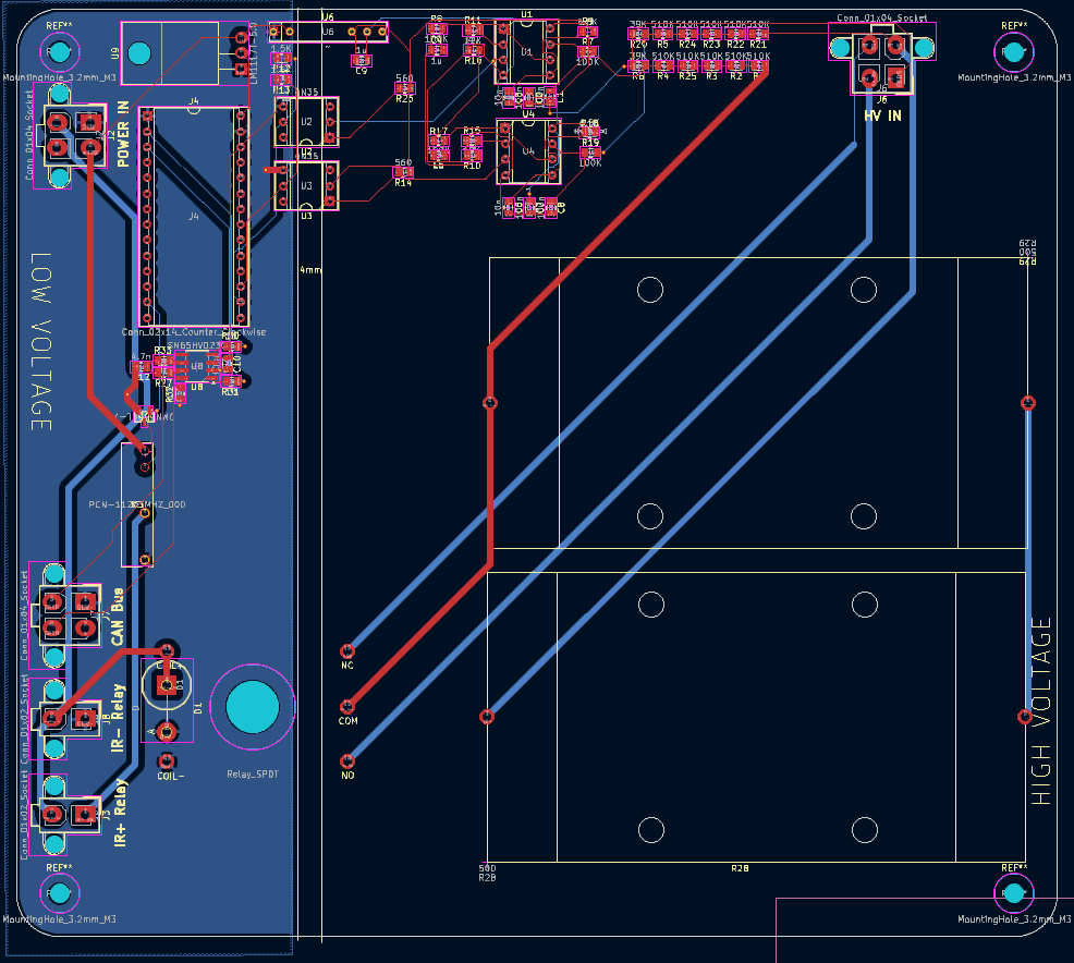
The PCC is split into two halves, high voltage (HV) and low voltage (LV). The HV side deals with accumulator and tractive system voltages which routinely go up to 400 V, while the LV side does not exceed 12 V. The FSAE rulebook specifies that there must be separation between these two voltage levels. However, we still need to communicate betweeen the two sides, as the teensy needs to read the voltages of accumulator and TS, both of which are on the HV side. In our circuit, this is accomplished using two optocouplers. Optocouplers achieve voltage separation utilizing an LED on one side (in this case HV) which will internally light up when there is a signal, and a phototransistor on the other side which will react to that LED.
HV Side
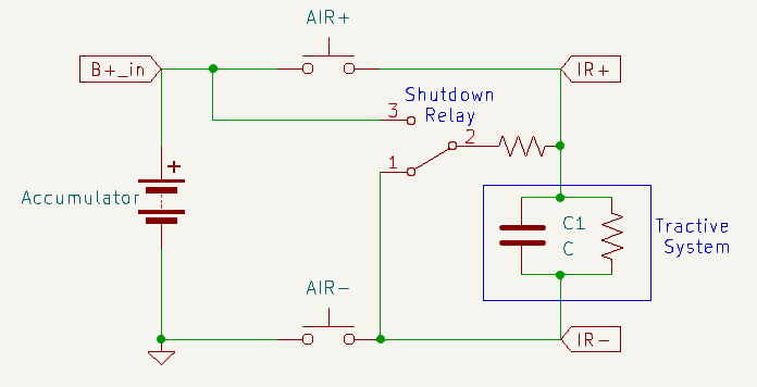
Here is a schematic demonstrating our system. The PCC is constantly reading accumulator voltage and tractive system voltage which come from B+_in and TS+, respectively. These are the most important connections to the system, and are fed into the board with a 2x2 molex connector. To read the voltages, the circuit utilizes two voltage to frequency converters, with input voltages that are stepped down with a voltage divider resistor network to be 1/10 of the actual value.
There are two Accumulator Isolation Relays (AIRs) in the PCC: AIR+ and AIR-. These AIRs are open air contact relays, capable of isolating very high voltages. In addition, there is a shutdown relay, which functions as a two way switch. We will refer to the shutdown relay as closed when it’s in position 1, and open when it’s in position 2. The precharge sequence and the states of these 3 relays during them is as follows:
Precharge: AIR+ is open, AIR- and shutdown relay are closed, TS is slowly and safely charged through the resistor. End of precharge: When TS+ is 70% of B+_in, the onboard teensy will tell AIR+ to close, bypassing the resistor. The system is ready. Error state: When we receive a shutdown signal through Shutdown_in or from a too fast/too slow precharge (see video for explanation if confused), AIR+/- and shutdown relay open. This configuration disconnects the accumulator and safely discharges the tractive system.
LV Side
Most of the complexity of the circuit are for the V2F converters, and those largely don’t need to be worried about. What is important to understand here is that the V2F converters convert an analog voltage to a signal with a frequency proportional to that voltage. Meaning: the V2F output signal is oscillating between 1 and 0. When vin is high, that oscillation will be faster, and when it is low that oscillation will slow down.
Using the optocouplers to maintain separation, that signal is fed to the teensy which then samples that data, and is able to control the rest of the circuit. The detailed implementation of these LM331 V2F converters involve capacitors and resistors which should be tuned to special values, but for this discussion of the PCC we will not dive into that.
Additionally, information on TS voltage, accumulator voltage, and error data are being sent over CANBUS to the CCM. This requires two teensy pins and utilizes a CAN transciever module.
Connecting Everything and Testing
Setting up the PCC can be confusing, and since it deals directly with accumulator voltage levels, it is important to understand how the wiring and connections work. Each of the connectors and what each pin is for are as follows:
HV IN TS+/-: positive and negative terminals of the tractive system B+_in: Accumulator-side AIR+ pin GNDS: Accumulator-side AIR- pin
POWER IN Shutdown_in: active high shutdown signal that triggers safe discharging of tractive system GLV-: Ground for GLV 12V: Positive terminal of GLV, or a 12 V power supply
IR+ Relay and IR- Relay Shutdown_in: active high shutdown signal that triggers safe discharging of tractive system GLV-, IR+_GND: ground signals
CAN Bus CANH/CANL: used for communication with CCM and other modules
Setup To test or use PCC, in addition to the board itself, you will need:
- two open air relays
- one 12 V source
- Accumulator or a 400 V power supply
- Motor+Inverter or some capacitor to represent the load
To hook up the accumulator to the inverter, take the two open air relays and decide which of them be AIR+ and AIR-. Connect one pin from AIR+ to Accumulator+ and one pin from AIR- to Accumulator-. The other pin of AIR+ goes to the positive terminal of the actual tractive system, and the other pin of the AIR- goes to the negative terminal of the tractive system. Definitely triple check this configuration. Make sure everything is isolated, it’s a good idea to use electrical tape over the contactors to avoid accidental shorting.
Now that the high-voltage components are hooked up, we need to connect the wires that allow PCC to monitor voltage levels. Connect the TS AIR+ pin to the TS+ pin of the HV IN connector, and the TS AIR- pin to TS-. Connect the accumulator AIR+ pin to B+_in, and the accumulator AIR- pin to GNDS. You will need to crimp wires and prepare a 2x2 molex connector.
Finally, we need to connect the PCC to the relays, so it can control them and open them in the case of a fault. The IR+/- ports correspond to AIR+/-, respectively. Simply connect them to their respective relays with Shutdown_in as the high input and with GND as low. After connecting CAN, the PCC is properly set up.
Software
Important Modules
General Overview
As mentioned in HV, the PCC is constantly reading the accumulator voltage and tractive system voltage and printing them to the serial monitor. As it does so, it transitions between five possible states: STANDBY, PRECHARGE, ONLINE, CHARGING, and ERROR.
- STANDBY (
void standby()): The initial/idle state of the PCC. Waits for a stable shutdown circuit (SDC). Opens accumulator isolation relays (AIR) and precharge relay. If the accumulator voltage is greater than or equal to the minimum voltage for the shutdown circuit (PCC_MIN_ACC_VOLTAGE), transitions into the PRECHARGE state. Also transitions into PRECHARGE if the BMS reports that charger safety is active (CAN_IsChargerSafetyActive()). - PRECHARGE (
void precharge()): Closes AIR- and precharge relay. Monitors precharge progress, which is a function of the tractive system voltage and accumulator voltage. If the precharge progress is completed (prechargeProgress >= PCC_TARGET_PERCENT), checks if the target percentage was reached too quickly. If so, transitions into the ERROR state. Otherwise, transitions into the CHARGING state if the BMS reports charger safety is active, or the ONLINE state if not. If the precharge is too slow, it will also transition into the ERROR state. - ONLINE (
void running()): The status that indicates that precharge has safely and successfully completed. Closes AIR+ to connect accumulator (ACC) to tractive system (TS) and opens precharge relay. If the BMS reports that charger safety becomes active (CAN_IsChargerSafetyActive()), transitions into the CHARGING state. - CHARGING (
void charging()): The state entered when the car is being charged by an external charger connected to the BMS. Keeps AIRs closed and periodically prints charger box data received from the BMS (pack voltage, charge current limit, rolling counter) to the serial monitor. Returns to STANDBY when the BMS clears the charger safety flag, and to DISCHARGE if accumulator voltage falls belowPCC_MIN_ACC_VOLTAGE. Transitions into ERROR if no BMS charger status CAN frame has been received withinBMS_CAN_TIMEOUT_MS(1500 ms), settingERR_BMS_CAN_TIMEOUT. - ERROR (
void errorState()): The PCC error status. Opens AIRs and precharge relay.
epoch refers to system time (?)
main.cpp
void setup(): Initializes GPIO pins and the precharge system.
void threadMain(): Continuously reads accumulator voltage and tractive system voltage and switches between the four states based on corresponding conditions.
precharge.cpp
getFrequency(int pin): Gets frequency of a square wave signal from a GPIO pin.
getVoltage(int pin): Converts the frequency into voltage for accumulator or tractive system GPIO pins.
prechargeInit(): Initializes the mutex and precharge task.
prechargeTask(void *pvParameters): Handles the state machine and status updates.
void standby(), void precharge(), void running(), void charging(), void errorState(): See General Overview.
float getTSVoltage(): Gets the tractive system voltage.
float getAccumulatorVoltage(): Gets the accumulator voltage.
PrechargeState getPrechargeState(): Returns the current precharge state (undefined, standby, precharge, online, or error).
getPrechargeError(): Returns current error information as an error code.
gpio.cpp
Initializes GPIO pins (shutdown control pin, accumulator pin, tractive system pin).
can.cpp
Handles CAN bus communication on CAN2 at 500 kbps: transmits PCC telemetry to the CCM and receives charger box data from the BMS. Two BMS frames are filtered in via the FIFO (everything else is rejected): the charger status frame (BMS_CHARGER_STATUS_CAN_ID = 0x185) and the charger command frame (BMS_CHARGER_CMD_CAN_ID = 0x306). Incoming frames are drained on a dedicated FreeRTOS task that runs every 2 ms, independent of the precharge state machine. Decoded charger data is held in a static ChargerData struct and exposed through accessor functions that use taskENTER_CRITICAL/taskEXIT_CRITICAL for atomic reads.
CAN_Init(): Initializes the CAN2 peripheral, sets the baud rate, configures FIFO filters for the BMS charger status (0x185) and command (0x306) IDs, and creates the canTask.
CAN_SendPCCMessage(state, errorCode, accumulatorVoltage, tsVoltage, prechargeProgress): Packs the current PCC state, error code, accumulator voltage, tractive system voltage, and precharge progress into a CAN frame and transmits it on the PCC CAN ID (0x222). Called once per precharge task cycle.
canTask(void *pvParameters): Dedicated FreeRTOS task that calls pollMessages() on a 2 ms period to drain the CAN rx FIFO.
pollMessages(): Reads any pending frames from the rx FIFO. On a charger status frame (0x185), decodes the safety flag from bit 3 of byte 6 (CHARGER_SAFETY_MASK = 0x08) and stamps the last-received tick. On a charger command frame (0x306), and only while charger safety is active, decodes the pack voltage (bytes 0–1, scaled by 0.1 V), the charge current limit (byte 2, scaled to A), and the BMS rolling counter (byte 6).
bool CAN_IsChargerSafetyActive(): Returns whether the BMS most recently reported charger safety as active. Used by the state machine to enter and exit the CHARGING state.
TickType_t CAN_GetBMSLastRxTime(): Returns the FreeRTOS tick at which the last BMS charger status frame was received. Used by the CHARGING-state watchdog to detect a BMS CAN timeout (BMS_CAN_TIMEOUT_MS).
float CAN_GetChargerVoltage(): Returns the last pack voltage reported by the BMS in the charger command frame.
float CAN_GetChargerCCL(): Returns the last charge current limit reported by the BMS.
uint8_t CAN_GetChargerCounter(): Returns the BMS rolling counter, used to verify that fresh charger command frames are still being received.
Improvements + next steps
- Clean up code (get rid of duplicate and unncessary comments)
- Replace B+_in and TS+ wire housings which barely fit inside 2x2 molex connectors
Author: Sebastian Ethan Basa
ORION BMS (Battery Management System)
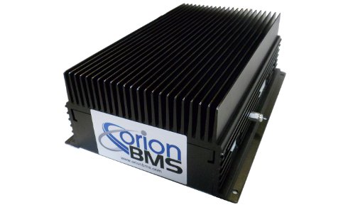
The purpose of the BMS is to monitor various aspects of the battery, protect its lifespan, and report any faults with the battery.
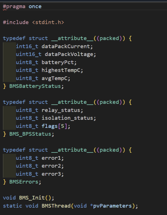
The BMS transmits data via CAN messages which have their own unique CAN IDs. Using C++ and FreeRTOS, we can retrieve the CAN data from the BMS in the form of data structs, which can be interpreted and used throughout the code to control the car. Some of the data values that the BMS can transmit include battery cell voltages, temperatures, battery health, and fault conditions.